Features - Technical
MAY 26, 2001
Carbon Fibre Technologies (CFT) Ltd.
BY PETER WRIGHT
Carbon Fibre Technologies (CFT) Ltd. is one of those companies that make up the backbone of the British motorsport industry.
|


Only a small number of racing car manufacturers, even among those making Formula 1 cars, can afford to staff and facilitate for their peak requirements, and then have people and machinery standing idle during off-peak periods. Instead, they set themselves up to meet the average requirements and out-source to cover the peaks. CFT provides just such a peak-lopping resource to a number of Formula 1 and other racing car and bike firms, and as such must meet their highest standards of engineering quality. CFT's period of maximum activity is from around November to April, during which the new season's cars are being manufactured, tested, crashed, re-designed and modified. 40% of CFT's turnover is in composites for motor racing and, in order to keep the factory busy during the rest of the year, it has expanded into industrial/telecommunication composites (50% of turnover) and aerospace composites (10%).
Having been born out of Formula 1 (Arthur was the head of Team Lotus's composites department in the early 1990s), CFT specializes in pre-preg. CFRP composites, as the name of the company implies. When composites (glass-fibre) emerged as the primary material for racing car bodywork in the late 1960s, many small companies started up to supply the needs of the industry. All it needed was a heated factory and a staff skilled in the use of a paintbrush and roller. Quality was variable, and it was not until carbon fibre began to be used as a true engineering material in monocoques etc., in the late 1980s, that the composite industry started to mature into one of the major players in motorsport engineering. CFRP is now used in around 80% of a top-level car, such as Formula 1, Formula 3000, GT or Sports Car. It is not only used in the cool, structural parts, such as monocoque, crash structures, suspension, body and wings, but it is also being used more and more in engine and gearbox components, to replace castings and fabrications in hot, highly stressed applications. Its further use is mainly limited by regulatory restrictions, rather than by the limits of the material properties. CFRP is now an engineering material that must be designed, engineered and manufactured to the same standards of precision and quality control as any other engineering material. However, its mechanical properties and manufacturing processes are so different, and in many ways more complex than metallic materials, that it has required a whole new set of approaches to apply it. Design tools, facilities and staff skills are all different to those used in, for instance, a fabrication or a machine shop.
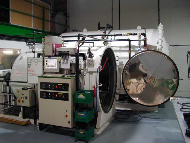
CFT has made just about all those component parts that make up the composite content of a modern racing car, mainly for Formula 1 teams including Arrows (others wish to remain nameless), and also for the Toyota GT One. To enable it to do so, CFT has invested in the facilities needed to perform all stages of the manufacturing processes. Two autoclaves are installed, one being 2.1m diameter x 3m long; the other is 1.5m diameter x 2 m long. Both are PC-controlled and histories of a complete cure cycle can be stored in the database.
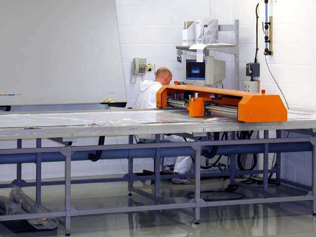
A Blackman and White pre-preg. fabric cutter is used for preparing sets of pre-preg. material for laminating a component. Also PC-controlled, it computes the optimum nesting of individual pieces, for minimum material wastage, and calculates an accurate figure for material used in the component as well as the total amount of material used, including wastage. The sheet of pre-preg. is unrolled onto an vacuum table and an X-Y cutter, using a tangentially-steered cutting knife, cuts out the fabric. It can also be programmed to replace the knife with a pen to label each individual part for identification during the laminating process. The shape of individual pieces can either be derived from CAD, or digitized from developed patterns. The machine has significantly reduced labor costs, the time to cut fabric and the wastage of high-cost materials. It guarantees precision and repeatability of material quantities - essential to ensure minimum weight and variation in finished components. A Formula 1 nose box is made up of up to 50 pieces of fabric, in around 5 layers, while a rear impact structure can have up to 270 pieces in its lay-up. A weight variation between components of less than 20gms in 4kg, i.e. 0.5%, is achievable, aided by this technology.
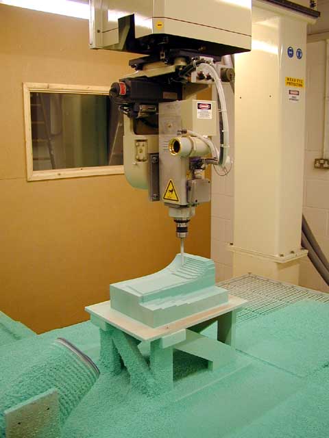
Although most Formula 1 teams provide machined patterns as well as drawings for components to be molded, it is not always the case. In order to avoid having to rely on sub-contact pattern makers, CFT has recently installed a Thermwood 5-axis router, with programmable tool-changing facility. This has a 3m x 1.5m bed and an extended Z-height of 0.9m. Tool-path software enables direct programming of the router from CAD files. Patterns can be machined in either aluminum, tooling block or graphite. The router is also used for machining of finished moldings, jigs and fixtures - an increasingly demanded facility now days.
Many customers, though not so much the motor racing ones, approach CFT with the concept design of a component to be made in CFRP. Often these components have been designed without detail consideration of how they can best be molded, and without the structural lay-up being specified. CFT uses SDRC's IDEAS CAD software to interface with the customer during the development of the design. This also enables them to interface easily with structural analysis consultants, Elston Engineering Services, to provide FEA analysis of composite structures. Composites are somewhat more complex to analyze than metallic structures, due to the anisotropic properties of the material. Different properties in the X, Y and Z directions of the fabric, interlaminar shear strength, variations in material properties with resin content, and the properties of core materials all have to be taken into account.
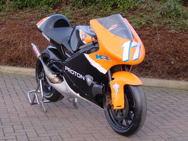
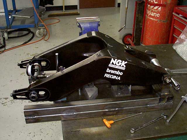
Recent examples of the development of critical CFRP laminate properties by FEA include the manufacture of a new, lightweight, high performance crash helmet shell. The ability to withstand impact, crush and penetration tests required a very complex lay-up. Components of satellite earth station antennae; the rear swinging arm for Team Roberts' 500cc GP motorcycle (this achieved a weight reduction of around 25% for a slightly stiffer arm, compared to the fabricated aluminum component); and the modification of a glider fuselage to accommodate a self-sustainer engine and pop-up propeller, are others.
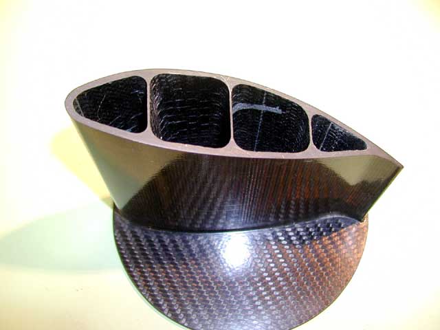
As CFRP is used for more and more structural components, the need to avoid multi-part moldings, bonded together, becomes greater. Structural designers want the load carrying fibres to be continuous, even through the normally bonded joints. CFT have developed a technique, using sealed and pre-shaped bags inside the moldings, which are inflated in the autoclave to consolidate the continuous fabric lay-up. Precise tailoring of the bags is necessary, and great dexterity on the part of the laminators is needed to place all the fabric patterns precisely inside complex and tight spaces in the molds. The picture of a rear wing mounting beam section shows a typical example of this technique, with the spars integrally molded inside the airfoil section.
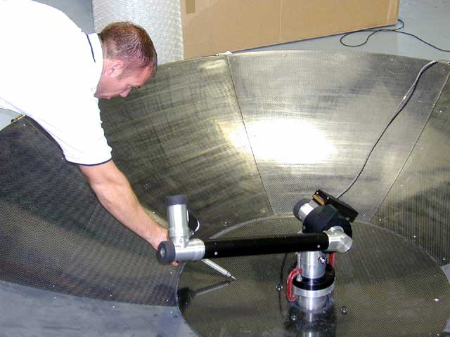
Quality control of composite component manufacture has two main aspects: dimensional tolerances and laminate/bond integrity. Measuring large and sometimes quite flexible components often presents major problems, and demands techniques appropriate to the particular component. By way of example, the accompanying picture of the profile of a large diameter satellite dish being checked, once the individual segments have been assembled, shows a FARO 3-D measuring arm being used. Arthur is not yet convinced that the latest ultra-sonic laminate inspection techniques are the best way to maintain quality during the manufacturing cycle. Composite manufacture is still a labor intensive process, and it is necessary to build the quality into the process, rather than inspect it in afterwards. For instance, many of the failures experienced in aircraft composites have been caused by the peel-ply layer being left in the laminate and causing de-lamination (peel-plies are laminated as the last layer of an intermediate stage, such that subsequent removal leaves a clean, roughened surface for the next stage). Ultra-sonic inspection would not pick this up, as it seeks voids; only conscientious staff prevents this sort of failure. The frequency of bond failures in wings and suspension components has increased as CFRP has been used in more safety critical areas of racing cars. The bonding of aluminum inserts and titanium suspension arm end-fittings into CFRP component moldings, requires absolute cleanliness and precise process control. CFT has developed the in-house techniques necessary to ensure that the demanded quality is achieved.
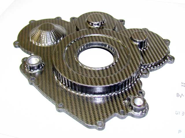
Apart from the motor racing teams, and the other products mentioned above, CFT has attracted a wide variety of customers. They work closely with Team Roberts (Kenny Roberts' GP bike team), developing not only the rear swinging arm, but also the fuel tank (lighter and cheaper than the aluminum one it replaces), structural seat unit, and an engine cover that includes bearing housings (see picture).
Lotus Cars, who are just down the road from CFT, has ordered low-production runs of CFRP parts for the limited-production 340R, and for lightweight racing versions of the Elise.
Much of the design of the satellite dishes was done in-house, to a concept and specification laid down by the customer. The need for low weight for low-cost transportability, and stiffness for precise pointing, dictated that these systems were made in CFRP.
Tooling for ducting for a regional jet, molded in pre-preg. Kevlar, and the glider project have been among the first aerospace applications. CFT welcomes one-off projects that require its special expertise and problem solving. Such a project has been the build of a 1/4-scale model of a novel floatplane. It was molded in CFRP as this was the only material capable of low enough weight, while maintaining the dimensional stability needed for scale flying and water trials of the concept.