The prime factors that differentiate the performance of one make of Formula 1 car from another in the current era of a single tire supplier are the engine and the aerodynamics. After the engine, it is the aerodynamics that commands the bulk of the R&D budget, with the team's wind tunnel being a major capital expenditure.
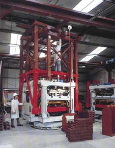
The prime factors that differentiate the performance of one make of Formula 1 car from another in the current era of a single tire supplier are the engine and the aerodynamics. After the engine, it is the aerodynamics that commands the bulk of the R&D budget, with the team's wind tunnel being a major capital expenditure. The lack of an in-house wind tunnel of sufficient size and sophistication is a serious holdback on technical progress. If there is any doubt about this, ask Jaguar. The effort to extract 5-6% improvement in L/D each year is getting to be harder and harder as the regulations restrict the scope for developments. These gains are made up of dozens of tiny improvements in all those small areas on the cars that constantly change in their detail configuration. Some of these changes are worth just 0.01-0.02% in the overall L/D and to find them requires an aerodynamic measurement system of great precision, large, precise models, inspired aerodynamicists, and hours and hours of time spent in the wind tunnel. That is why teams spend a lot of money on their aerodynamicists and more than $15m on their wind tunnels.
Once the earth has been moved, the steel structure fabricated, and the electrical lines for Megawatts of power for the fan have been brought in, a wind tunnel only provides a means of simulating an object moving through the air; it does not tell you what is happening to it. Racing car vehicle dynamicists want to know the forces on the car, and the aerodynamicists want to know how those forces are generated and how to modify them. For this, the wind tunnel and the models must be equipped with a range of measurement and visualization systems, and the simulation must be extremely precise if the results are to be reliable. Providing the hardware and software for this is a specialist task. The majority of Formula 1 and other leading racing car companies have turned to a UK company, Aerotech A.T.E. Ltd., to provide many of the systems they need.
 |
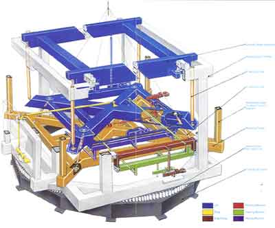
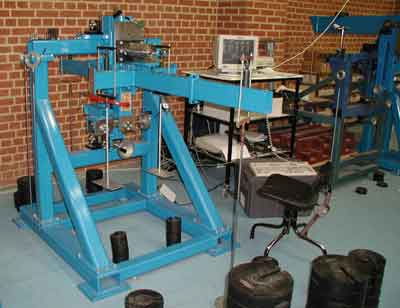
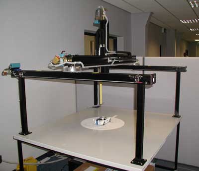
| Figure 2: Overhead balance |
|
|
Aerotech was founded in 1985 by its Managing Director, Mervyn Cullimore. It is based in Heathfield, East Sussex, with a North American branch in Tullahoma, Tennesse. Originally the majority of its customers were the aeronautical industry and University research laboratories, but the upsurge in motor racing investment has resulted in this industry growing to 50% of Aerotech's business, while aerospace and the road car industry each represent 25%. As with everything that surrounds Formula 1, many of the teams do not want anything to be known about their future plans. However, Aerotech lists Benetton, BAR, Ferrari, Jordan, Lola, Reynard, Swift and Toyota Motorsport among their customers, and is currently bidding to build a complete, 50%-scale, multi-user motor racing wind tunnel.
The quest for greater accuracy in aerodynamic testing has pushed up the scale to which the wind tunnel models are built from 25% in the 1960s and 70s, to 50% for most current Formula 1 testing. Toyota Motorsports are building a new model tunnel in Cologne for the development of their Formula 1 entry. To achieve the highest possible, and hence most representative Reynold's Number, speed must also be as high as possible. As tunnel size - 65% scale is rumored to be the next step - and speed go up, the cost of building and running these large wind tunnels increases exponentially, and the means of keeping the tunnel cross-section small for a given model size is being actively sought. The problem is one of blockage - the ratio of the
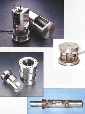 |
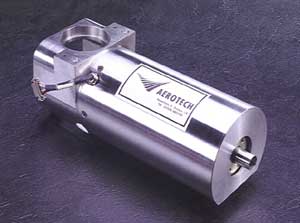
| Figure 3: A variety of internal balances manufactured by Aerotech |
|
cross-section of the model to that of the working section. The maximum cross-section area permitted for a Formula 1 car is around 1.5m2, so a 50% model is 0.375m2. If the working section has straight walls with a small divergence to account for boundary layer growth, a blockage of 3-4% is acceptable. Anything greater causes a local acceleration of the flow around the model while the walls influence the pressure distribution on the model. Thus a 50% tunnel, with straight walls, must have a cross-section of around 9-10m2 at the model test area. Slotted walls are sometimes used, which impose less constraint on the flow and even out the pressure along the length of the working section, raising the acceptable blockage to 6-7% and thus halving the cross-section area required. Latest generation wind tunnels have working sections with adaptive walls - the sides and roof are flexible, with actuators spaced every meter to automatically adjust the profiles and maintain a constant pressure along the length of the working section. This technology, though expensive in itself, permits blockage values as high as 10-15%. This has two potential pay-offs: either the whole wind tunnel can be scaled down for a given model size, with significant capital and running cost savings; or larger models can be tested in a tunnel originally designed for say, 50% models. By fitting a new adaptive-wall working section to replace one with solid surfaces, the acceptable blockage rises by a factor of 4 or 5, and the maximum model size increases from 50% to full size. Business from this new technology could easily grow in the coming years, as teams strive for ever-greater accuracy.
The core of Aerotech's business is the design and manufacture of wind tunnel force balances i.e. the means of measuring the forces on models. Any moving object, whether car, aeroplane or other, has three forces and three moments generated by the flow of air over it and these 6-components must be resolved and measured. The hardware for accomplishing this can be mounted either above or below the working section, with the model attached to it and the virtual center of the balance located within the model. Alternatively the balance can be inside the model, mounted on the end of the support strut. Aerotech has seen a trend in Formula 1 from internal balances to external ones. When tunnel testing became the norm in the 1970's, most
 |
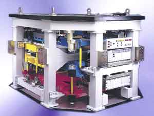
| Figure 4: external balance during calibration |
|
teams used research laboratory wind tunnels, which were fitted with external balances. However, as demand on these facilities increased, teams found that they had to use a number of different tunnels to make up the testing time they wanted, and designed their models with a bespoke, internal balance so that the model could be mounted identically in the different tunnels. As teams built their own tunnels, they have returned to using external balances, freeing up space within the model for other measurement equipment, and car and wing attitude control systems.
A wind tunnel balance takes each of the three forces and three moments and "feeds" them to a load-measuring element for each component. Load measurement is either by a strain-gauge load cell, or a null reading weigh beam (the position of the weight is servo-controlled to achieve a balance, thus balancing the load without the small deflection required by a strain-gauge load cell). The mechanical arrangement necessary to measure each of the components independently and resolved to the virtual center, is quite complex. Figure: 1 shows a schematic layout of an under floor balance , and Figure: 2, an actual overhead balance . Internal balances effectively compress the whole structure into a small space, by machining a series of strain-gauged and flexure elements into a monolithic structure. A variety of internal balances manufactured by Aerotech are shown in Figure: 3 . The exact arrangement of Aerotech's 6-component, internal balance is a company secret.
However precisely constructed, such complex mechanical structures possess non-linearity, hysteresis and cross coupling between the individual components. To achieve the required accuracy: 0.1-0.2% of full-scale deflection for an internal balance, 0.04% FSD generally, and 0.02% for Lift and Drag on an external balance, the completed system must be calibrated. The balance is loaded for each component and in combination, to generate a 6 x 27 term matrix containing the coefficients for 6 linear, 6 quadratic and 15 cross-product terms for each aerodynamic component. The software that takes the data from the 66 individual load runs, producing 1000 data sets and 6000 individual load cell outputs, and then calculates the 162 coefficients in the calibration matrix, is another of Aerotech's "crown jewels" and is not for sale even to it customers who purchase balances. Figure: 4 shows an external balance during calibration , and Figure: 5 an internal balance undergoing the equivalent process . To maintain the accuracy, the temperature within the balance enclosure is conditioned to 25?C ±0.5?C.
 |
| Figure 5: internal balance during calibration |
|
Formula 1 models possess an additional complexity in that high pressure air is fed through the model to simulate exhaust flow and any forces the ducting generates as it passes from the fixed, ground side of the balance, to the measured side, must be taken out with additional coefficients in an enlarged matrix. Figure: 6 shows such a balance .
Aerotech also builds strain-gauge load cells for measuring the forces on individual wings mounted on the model, and for the drag measurement of wheels, which are mounted independently from the model. Measurement of the lift force on rotating wheels, which run in contact with the moving road belt, is much harder, but load cell systems mounted under the belt and measuring the vertical component of the contact patch load are being developed.
Aerotech can integrate an internal balance with a model motion system, to provide automated attitude control for multi-test point runs. Figure: 7 shows a schematic of such an installation in an open-cockpit car model .
 |
| Figure 6: As high pressure airit passes from the fixed, ground side of the balance, to the measured side, must be taken out with additional coefficients in an enlarged matrix. |
|
Software for automatically running through a series of car positions and wing incidences, and for data acquisition and post processing of the results can be provided to any level requested by the customer. The raw outputs from the balance can be interfaced to the customer's own data and analysis system.
Presented with files of force coefficients, aero maps etc., the aerodynamicist knows exactly the characteristics of each configuration tested, and can pass these results to the vehicle dynamicists for their simulation work. However, trial and error is an inefficient development method, and has a limited place in the current high tech approach to Formula 1. Aerodynamicists need to know how a modification has altered the flow and pressure fields around the model and in order to better understand the highly complex aerodynamics of an open-wheeled car, he needs to carry out basic research. For both these tasks, he needs tools that enable him to visualize and measure certain key characteristics of the airflow. The forces on a body such as a racing car are the sum of the pressures acting on the surfaces, and it is normal for models to be covered in static pressure holes, laser-drilled normal to the surfaces, especially those involved in the creation of lift or downforce. Pressures are sampled either with a Scani-valve, or digitally, via a bank of solid-state pressure sensors.
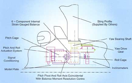 |
| Figure 7: Schematic of an installation in an open-cockpit car model |
|
This data provides information on the distribution of the forces that make up the 6-force coefficients, but it requires skill and experience in its interpretation to yield information on the flow characteristics that cause these surface pressures, because they are just that: surface pressures. What is going on away from the surface is not normally visible and on an open-wheeled car with its large areas of separated and vortex flow, extremely complex. What is needed is a means of inserting probes into the flow at any point, for the measurement of velocity (magnitude and direction), pressure, and turbulence level, and knowing the exact position of that measurement. With automated surveys, sampling and data reduction, maps of air velocity, energy, pressure, vorticity and turbulence can be plotted all around the car and in its wake, revealing a picture of the flow conditions that exist for any test configuration. The mechanism that inserts and positions the probe must not itself disturb the flow to the extent that it alters the flow field in the locality of the probe. Aerotech design and make such devices and the software to control them.
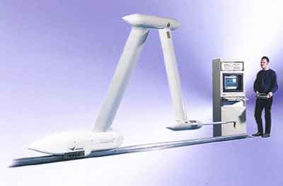 |
| Figure 8: Aerotech’s rail-mounted, rotary probe survey system |
|
Aerotech's probe survey systems are either rail-mounted, rotary systems (Figure: 8) , or X, Y, Z traverses (Figure: 9) . The rotary system has a 3.75m reach, and can survey a volume 6m x 3.4m x 2.6m from a single rail, either floor or roof mounted. Additional rail positions will extend this volume. The arms are constructed in CFRP for low weight and high stiffness. Nominal position accuracy is ±3mm, but this can be improved to ±1mm by locating the probe position with a laser and closing the position loop around its position, thus compensating for any aerodynamic deflection of the arms.
The X, Y, Z traverse is suitable for larger wind tunnels; the one in Figure:9 is a working model, built for the purpose of software development. The full size traverse is destined for a Chrysler wind tunnel and will traverse across a span of 17.5m in the working section.
The types of probe commonly used include 5-probe, total energy/flow direction; static pressure; hot-wire anemometer; and microphones for acoustic measurements - an area of growing importance on road cars in the quest to eliminate wind noise. It is no good searching out sources of wind noise around A-pillars and wing mirrors, with sensitive microphones, if the airflow in the tunnel is inherently noisy. Major noise generators are the turning vanes in the corners of the wind tunnel duct itself, and these are now being designed using CFD to ensure that they generate minimum turbulence.
 |
| Figure 9: Aerotech’s X, Y, Z traverse probe survey system |
|
Cullimore does not see that CFD will present a threat to Aerotech's business as a "wind tunnel in a computer". Rather he believes that it will create an increasing need for greater wind tunnel accuracy in order to validate the codes as they are developed. Formula 1 continues to demand new and improved facilities, with the quest for better simulation though testing at a larger scale and higher Reynold's Number, and more accurate measurement. Road car facilities offer growth, particularly as manufacturers seek better representation of the ground plane. Many of the existing tunnels used for road car testing are fitted with under floor balances, and a moving ground plane is thus not a viable option. The typical ground clearance of road cars and the low lift/downforce figures probably make a full ground simulation unnecessary. Aerotech is involved in the development of ground simulation technology called Boundary Layer Injection and Suction System (BLISS). The boundary layer is removed ahead of the vehicle and the air that is bled off is re-injected downstream of it, in order not to change the air mass in the tunnel. The boundary layer will grow from behind the suction area, but will be much thinner than the normal boundary layer on the floor of the tunnel. This relatively simple and low cost solution can provide a very reasonable degree of simulation for full size testing of road cars, particularly when retro-fitted to existing tunnels.
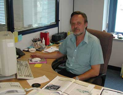 |
| Figure 10: Aerotech’s founder and Managing Director, Mervyn Cullimore |
|
Aerotech has established itself as a supplier in several niches of the wind tunnel industry, and is prepared to take on any part of or all of a new tunnel facility, where it believes it can provide a high quality product. It has recently bid for and hopes to win the contract to replace the wooden fan blades in a 40-year old NASA wind tunnel, which have come to the end of their design life. The fan consists of 10 blades, each with a span of nearly 5.0 meters, and a root chord of 1.5 meters. The fan diameter is 14.5 meters, and the hub diameter is 4.6 meters. There are many such wind tunnels in the USA, mostly belonging to NASA. Most of them were built in the 1960s, and are coming up for renewal of the fan blades. Laminated wood is the ideal material due to its damping properties, but there are few companies who have the skills to make them. Aerotech saw the market potential of supplying new blades and combining their expertise and ISO 9000 quality control procedures with the wooden boat building technology available on the South coast of Britain. They decided to go after the business.
Aerotech is one of those companies that, equipped with the technology that Formula 1 demands, has been able to adapt itself to the requirements of supplying an industry that wants the very best - yesterday. Each successive customer wants something that is a little bit better, faster, more accurate and smarter than the previous one with whom he competes on the track. Aerotech's development in order to serve such demands has undoubtedly been a strong influence on the company, both technically and from a customer support point of view, to the benefit of its road car, aerospace and research laboratory customers.
Figure: 10 - Aerotech's founder and Managing Director, Mervyn Cullimore.