Features - Technical
JULY 21, 2001
Barriers
BY PETER WRIGHT

The ideal crash barrier is no barrier at all. However, the only applications of this in motor sport that I can think of are at Bonneville and the Black Rock desert, used for Land Speed Record attempts. At these sites there are several miles in every direction between the track and the mountains and, even through a telephoto lens the vehicles seem a very long way away from the spectators and viewers. Barriers are necessary on race circuits to enable spectators and TV cameras to get close enough to the action, without being exposed to the danger of being hit by an out of control car.
The problem is little different from stopping a train ploughing into the platform and injuring potential passengers when the driver has left the braking too late. The buffer is equipped with energy absorbing devices (large spring/dampers) which engage with similar devices on the front of the train. The energy is absorbed and dissipated and the train brought to a halt without damage or too great a shock to the passengersÉ. provided the capacity of the joint energy absorbing system is adequate. Road and racing car barrier systems work in a similar fashion: both cars and barriers have energy absorbing devices, which engage and dissipate the kinetic energy of the car. However, while trains are perfectly aligned, buffer to buffer, by the rails, cars can hit a barrier pointing in any direction, at any height, and either spinning, rolling, tumbling end over end, or some complex combination of all of them. The energy must be dissipated without either subjecting the car to loads that cause the driver protection structure (safety cell) to fail and injure the driver by intrusion, or subject the driver to decelerations that cause internal injuries or result in him striking the safety cell, especially with his head. The magnitude of the energy to be absorbed and dissipated increases as the square of the speed: at 100kph it is the equivalent of dropping the car from a height of 78 meters; at 200kph - 314 meters; at 300kph - 707 meters. Loss of control of a racing car at the end of a straight is the equivalent of falling from an aircraft flying at a height of nearly _ kilometer.
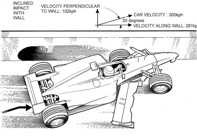
The mechanisms used by the car and barrier energy absorbing systems vary. The Formula 1 Technical Regulations stipulate a series of tests on frontal, rear and side impact structures that results in short, stiff, sacrificial structures that dissipate energy by material failure. The highest performance of these tests - the frontal impact test - generates peak loads of 460KN (60g), 300KN (40g) average, and dissipates the energy equivalent to a fully loaded car travelling at 50kph in little over 0.5 meters. Barriers tend to be more like train buffer systems, behaving like spring/dampers. They absorb energy by deflection, dissipating some of it via the damper part, and storing and releasing again the remainder, via the spring. This latter causes rebound, which I will come to shortly. Some barriers also slow the car by momentum transfer: the car collects heavy parts of the barrier, and by the principle of conservation of momentum, its speed is reduced proportional to the increase in the mass of the car plus the barrier. Fig.1 shows a car hitting a two row tire barrier, spaced in front of a three row barrier. When it hits the first rows it collects an ever-increasing mass of tires, which combines with the mass of the car to reduce its velocity by momentum transfer, prior to impacting the second set of tires. In fact, most barriers combine momentum transfer, material failure, spring and damper in a complex interaction. Pure material failure (crushable) barriers such as Armco and foam blocks, have not found the favor one might expect as they are one-shot systems, and there is a racing requirement to replace barriers as soon as they are damaged. Spring/damper barriers usually recover, to be capable of absorbing further impacts.
By far the biggest challenge facing a circuit barrier designer is to come up with a construction that accommodates a variety of angles of impact and is stiff enough when impacted with the front or rear of the car, but not too stiff when hit with the full length of the car travelling sideways. Modern single-seaters have sharp pointed noses, reinforced to absorb frontal impacts. They are just like stilettos, and tend to penetrate barriers like a knife through butter. There is not much substantial behind the nose to engage with the barrier until the wheels, which if attached with CFRP suspension offer little resistance. It is not until the side pods are reached, or the wheels jam into the front of the side pods, that there is anything to really slow the car. In a side impact however, the wheels and side pods, which are full of impact structure and crushable radiators and exhaust, engage over 3 meters of a barrier. Both cases must be catered for and the barrier characteristics are inevitably a compromise. No one barrier system is ideal for all situations, and the solutions vary according to the site on a circuit. It is not possible to accurately predict how and where a car will impact, but it is possible to make reasonable estimates of where they are most likely to.
|
|||||
Temporary road circuits are often built using connected concrete blocks, as are sometimes used as temporary barriers on roads. When a car hits one of these, it may actually move one or more blocks, each of which weighs over a ton. The action of moving the block increases the instantaneous effective mass of the car, and hence reduces the velocity by momentum transfer. The friction between the block and the ground then dissipates the energy in the car and block. Moving a block just 0.5 meters may well halve the severity of the crash pulse. Concrete looks pretty unforgiving as a barrier material, but in the right application it serves very well. It also withstands impacts without much damage, and so does not require refurbishment or replacement before racing can continue.
Lining the edges of the track with a rigid wall does not work once the geometry of the circuit causes perpendicular impact velocities above about 60-80kph i.e. when straights lead into corners that require the cars to brake heavily to reduce the speed of entry. In these cases the barrier itself must be able to absorb significant amounts of energy, but even the best barriers are not yet able to stop a car from high speeds in a short distance. The approach taken is to use as much space as is available to slow the car. Run-off areas are provided to generate a low level of deceleration (around 1g), and to enable the driver to attempt to sort it out and rejoin the track, and the boundaries are lined with barriers, the specification of which is determined by the likely residual velocity and the direction of impact. The thickness of the barrier is one of the most critical parameters that determine its performance - the greater the distance available to decelerate the car, the lower the average deceleration g-level and the softer the barrier can be constructed. However, if the barrier is too thick and soft, the car may penetrate it so deeply that the barrier face reaches the driver's cockpit and injures him, or traps him and hinders rescue. Similarly in an oblique impact, where the velocity along the barrier is high, penetrating the barrier can snag the car, and then the car stops so abruptly that the driver is injured by the high deceleration, or the car turns over. Examination of the videos of Jacques Villeneuve's Eau Rouge accidents at Spa in 1998 and 1999 show a barrier subjected to high speed oblique impacts, fortunately ones in which the barrier design protected him well.
|
|||||
Tire barriers were first used in the USA, and started to be adopted in Europe in the 70s. They gained favor as being an extremely practical way of building barriers in a variety of configurations and of providing a reasonable degree of protection. Used tires are plentiful in every country in which motor racing takes place, barriers can be assembled by unskilled labor in a range of thickness and module lengths, and tires weather well and survive minor impacts without damage and so do not need replacing regularly. All this adds up to a feasible, low cost barrier system. The only serious, practical problem I have heard of is that they collect rainwater and provide ideal breeding grounds for mosquitoes! Tires deform as springs, and so there is some rebound. However, energy is dissipated by the action of tearing the tires (especially where they are bolted together), friction between the tires, and by the friction between the tire stack and the ground
However, the assessment of the impact performance of tire barriers was based on accident outcomes rather than any scientific tests, until the 90s when the FIA started impact trolley tests at the CSI Laboratory in Italy, and GM carried out tests at Wayne State University in the USA. These early tests looked at the effects of the various tire-stacking configurations that were popularly employed, the connection systems between the tires (e.g. bolting, strapping, chains), and the number and placing of the rows of tires. The impact trolleys all had blunt, rigid impactor faces and so provided comparative data rather than the actual performance of a racing car hitting the barrier.
When Senna died at Imola in 1994, there followed a surge in barrier concepts offered to the FIA for consideration. Many of these were commercial systems used on roads or new concepts utilizing materials manufactured by the company promoting the idea. The FIA decided that a new barrier test procedure was needed to represent better the impact by a stiff, sharp-nosed single-seater. The Transport Research Laboratory (TRL) in the UK, was commissioned to develop this test and to use it to evaluate the performance of existing barriers and the better ideas that had emerged in the aftermath of Senna's accident. The test would become the method by which any novel barrier system could be evaluated.
|
|||||
Ideally, barriers would be tested through a range of impact angles. However, once the impact is other than perpendicular to the barrier, the dynamics of the trolley come into effect and significantly alters the outcome. To accurately simulate the dynamics of a single-seater racing car one needs just that: a single-seated car. Even using damaged and repaired F3000 cars for the tests would be prohibitively expensive. There is an additional problem in that racing tires have such a high cornering stiffness that they react to any road surface irregularity and steer the car, making it extremely difficult to guide it automatically even at 80kph. Barrier tests in the USA on an IRL car resulted in a spectacular crash, but not against the barrier! Data from CART and IRL cars on ovals has shown that drivers consistently survive side and rear impact that generate of the order of 150g, without injury, thanks to current seat and head protection padding. The critical impact direction is head-on and about 30 degrees either side. A well-restrained driver should be uninjured in a frontal impact of 30g, and this should increase to at least 40g if he is wearing a HANS device. Thus it was decided that a frontal test is the critical case for barrier design.
Tests were carried out on three rows of tires, to evaluate:
- Tire fixing methods - straps and bolts
- Separating the front 2 rows from the rear row
- Inserts in the tires - foam cylinders and plastic tubes
- Additional mass by fitting smaller tires inside the primary tires
- Fitting conveyor belting to the impact face
The resulting deceleration traces were analyzed to determine the energy absorbed by the barrier, the energy absorbed by the nose cone, stored (rebound) energy, and peak and average decelerations. Fitting plastic tubes inside the tires (the tubing used is similar to that used for underground gas mains) doubled the energy absorbed by the barrier. Conveyor belting contributed little in a frontal impact, in fact it slightly increases the rebound, but it does prevent the car snagging in an oblique impact.
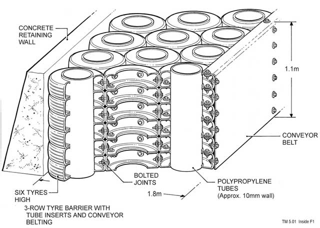
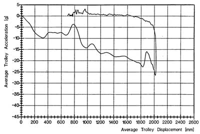
The best configuration of barrier - bolted tires, tubes and conveyor (see Fig.3) - was tested at 80kph (77% more energy), at which speed it absorbed nearly 80% of the trolley's energy, the nose absorbing the rest, without exceeding 30g - See Fig.4 - the final peak is the nose crushing. Fig.5 is a section of the high-speed film of the test, with the sequence running from right to left, at 20 millisecond intervals.
The car is brought to a halt from 80kph in just 2 meters - the depth of the barrier plus the length of the nose cone crush - averaging 12.5g. If the two energy-absorbing systems could generate a steady 30g for the 2 meters available, the car could be stopped from 123kph. If the driver can stand 40g, this goes up to 143kph. These figures give some indication of the potential and difficulties of barrier and car design.
|
|||||

A number of other, proprietary barrier configurations have been tested, but the results are confidential to the companies involved. In many tests the effect of the sharp nose cone has surprised the designers! A design approach that is popular is embodied in the Airfence system, developed as a temporary barrier for roads works, used in critical areas at Monaco for instance, where the available space is limited. The barrier is made up of air filled cells that exhaust through metering orifices when impacted, in much the same way that an airbag works. The barrier is made of strong, flexible plastic, and provided the car does not penetrate it, it recovers for further use.
In the USA, with its many high-speed oval tracks, the search is on for a barrier that provides some impact absorption in the perpendicular direction, while retaining all the good qualities of a concrete wall i.e. no damage, no snagging along the wall, no rebound. A barrier that deflects up to 0.5 meters while retaining a smooth profile, would about halve the massive g-levels sometimes experienced during impacts. Meanwhile, in Europe work is underway to increase the absorbed energy during a head on impact. Not only must the magnitude of the resulting crash pulse be defined, but its shape can have an effect on the injury outcome. Advanced, high-performance barriers must be developed hand-in-hand with the safety features on the cars, driver protection systems and be based on biomechanics research into human tolerances. Component failure at the end of a straight, or two cars touching early in the braking area, provides the most critical safety conditions for both the run-off area and the barriers. If the cars become airborne across the run-off area, they may arrive at the barrier with little loss of speed. The challenge is to ensure the driver is not seriously injured and the spectators are untouched.
With all the effort going into barrier research, the safety of competitors and spectators still comes down to ensuring that the correct and latest safety systems are installed and maintained at circuits around the world. The effort and negotiating skills needed to achieve this are enormous.